The BIM-How To? 2025 conference, organized by TeamCAD, was held on October 16th in the beautiful setting of Madlenianum Theatre in Zemun, gathering numerous professionals from the fields of architecture, construction, mechanical engineering, and information technology.
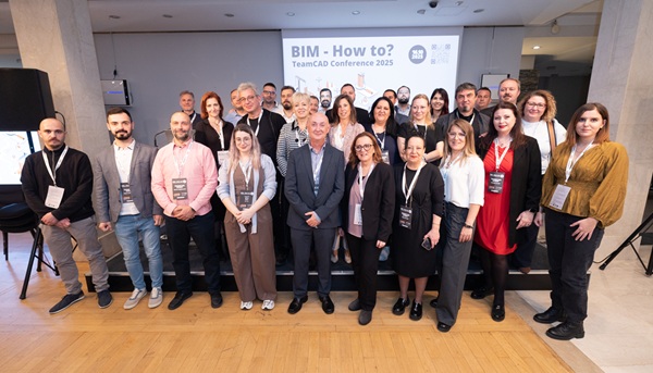
This year’s event aimed to showcase practical examples of BIM technologies and digital tools, while also opening a dialogue on challenges, standards, and skills shaping the future of the construction industry.
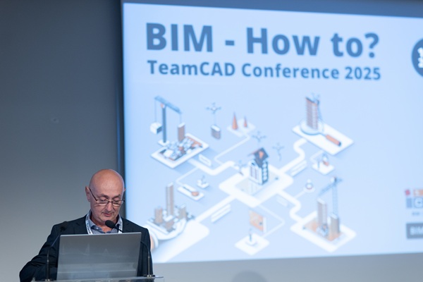
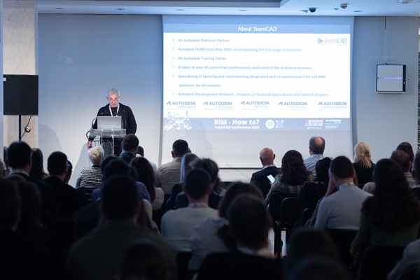
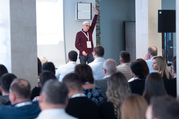
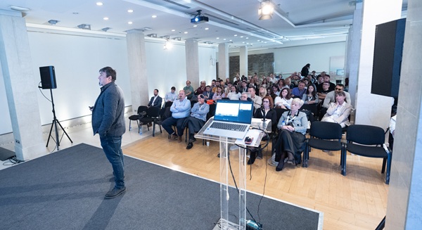
The conference began with an opening speech by Slobodan Lazić, Director of TeamCAD, who welcomed all attendees and delivered an inspiring introduction.
Session 1: From Practice to Tools
The first presentation, “How (not) to BIM? Learning through mistakes”, was delivered by Mina Esov, BIM Manager at Servisa, who demonstrated how experience — and even mistakes — can lead to a deeper understanding and improvement of BIM processes.
Next, Dmitry Brickman, Director of Development at TeamCAD Israel, presented VEGA AutoCAD add-on, a tool designed to enhance AutoCAD workflows through automation and intelligent features.
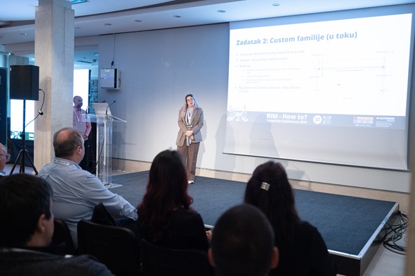
Tara Badnjar, Junior AEC Application Specialist at TeamCAD, followed with a talk on the Scan to BIM process, highlighting how laser scanning can improve the precision of existing condition modeling.
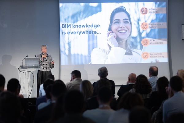
The session concluded with Marina Korol, independent consultant, who discussed openBIM Practitioner Certification and emphasized the importance of internationally recognized competencies and standardized approaches in the BIM environment.
After an inspiring first block, attendees took a coffee break in the foyer, using the opportunity to network and exchange ideas.
Session 2: From Strategy to Standards
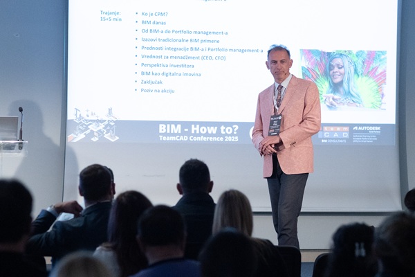
The second session opened with Milan Šmigić, Founder and Director of the Center for Project Management (CPM), who presented From BIM to Portfolio Management - exploring how digital project management supports strategic decision-making.
Then, Dejan Trkulja, Founder and Director of Trkulja Consulting, spoke about The Role of ISO Standards in Information Security for Construction Projects.
Following him, Vuk Vukanić presented ISO 19650 and Autodesk Construction Cloud, showing practical ways to apply international standards in digital project workflows.
During the lunch break, participants had the chance to connect with speakers and partners, and to share experiences regarding BIM implementation in their organizations.
Session 3: Digital Platforms and Tools
After the break, Hasan Bora Yavuz from Autodesk presented Autodesk Industry Clouds, highlighting the role of cloud solutions in connecting teams and data across the project lifecycle.
Next, Zoran Šobić, Founder and Director of ICH, shared BIM Onboarding Playbook: From Example to Implementation Methodology, outlining practical steps for successfully adopting BIM methodologies within organizations.
The session wrapped up with Vladimir Guteša, Director of Development at TeamCAD, who demonstrated TeamCAD Revit Tools - a set of tools developed to accelerate and simplify everyday work in Autodesk Revit.
A short refreshment break before the final session gave attendees another opportunity for informal networking.
Panel Discussion: What Makes a Good BIM Model?
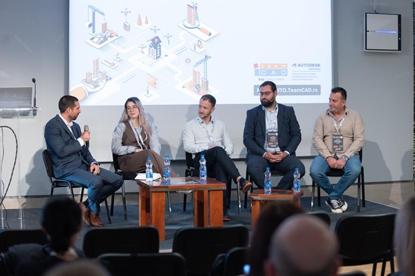
One of the most anticipated moments of the day was the panel discussion “What Makes a Good BIM Model?”
The session was moderated by Vuk Vukanić, who was joined by Vladimir Mladenović (World of BIM), Mina Esov (Servisa), Aleksandar Popadić (Hybrid Technical Solutions), and Aleksandar Stanisavljević (BeeBIM).
Panelists shared their insights on the quality and value of BIM models in real-world projects. The discussion raised important questions and confirmed that collaboration remains the key to successful BIM implementation.
Prize Draw and Closing Remarks
The conference concluded with the traditional prize draw, where participants had the opportunity to win valuable gifts.
The closing message emphasized that BIM-How To? has become more than a conference, it is a true meeting place for knowledge, collaboration, and growth within the regional BIM community.
TeamCAD extends heartfelt thanks to all speakers, panelists, participants, and partners for their trust, enthusiasm, and continued support, which make this event truly special every year.
Special thanks go to our sponsors: Autodesk, TD SYNNEX, CPM, and TeamCAD Israel for their partnership and contribution to making this conference possible.
For any questions regarding BIM tehnology, Vega software or TeamCAD Revit tool, contact us at This email address is being protected from spambots. You need JavaScript enabled to view it.